Received- May 14, 2019; Accepted- June 1, 2019
International Journal of Biomedical Science
15(2), 68-75, Jun 15, 2019
© 2019 M. Anand et al. Master Publishing Group
A Finite Element Study on Comparision of Stress Distribution around the Vertical and Angled Abutments in Implants
M. Anand1, Gulab Chad Baid2, H. S. Mohammed1, Prasad A. Hari1, Vinaya Kundapur1, M. U. Swetha1
1 Department of Prosthodontics, MRADC, Bangalore, India;
2 Department of Prosthodontics, Maitri College of Dentistry and Research Cente, Anjora, Durg, India
Corresponding Author: Dr. Vinaya Kundapur, Senior Lecturer, Department of Prosthodontics, #1/36, Cline Road, Cooke Town, MRADC, Bangalore 560005, Karnataka, India. Phone No: +918904073488; E-mail: drvinni@gmail.com.
Running title: COMPARING STRESS DISTRIBUTION AROUND IMPLANT ABUTMNETS
|
|
ABSTRACT
 |
Background: Appearance or aesthetics play an important role in the lives of most people specially professionals and any restorations with less than optimal aesthetics will probably not acceptable. Dental implants have earned an excellent reputation for Biocompatibility, Predictability and function throughout the past decades. Use of angulated abutments may be the method of choice when anatomic limitations preclude the axial placement of an implant. A variety of pre angled abutments are available at specific divergence angles, additionally, custom angled abutments may be cast to profile necessary for an acceptable prosthetic outcome. Objectives: The purpose of this study was to evaluate and compare the stress distribution around the vertical (0 degree) and angled (15, 20 degree) abutments in implants. This study was carried out under a vertical force of 100 N and horizontal force of 50 N respectively for all the situations. Materials & Methods: A 3D finite element model was made of anterior maxillary right canine region using the details from the CT scan using the computer software (ANSYS 11). A stimulated 13 × 4.2 mm implant was placed in the centre of the b one and its superstructure was created. Two different loading conditions for 3 different abutment angulations (0, 15, & 20 degree) relative to long axis of implant were applied. The stress generated in the cortical and cancellous bone around the implant was recorded and evaluated with the help of ANSYS. Resuts: It was shown that on vertical loading and horizontal loading of 100 N and 50 N respectively on zero degree angulated abutment, the Von Mises stresses were seen to be uniformly distributed all along the implants in the cortical and cancellous bone. It was also shown that vertical and horizontal loading of 100N and 50 N respectively produced maximum stresses n both cortical and cancellous bone around the neck of Implant for both the 15 degree and 20 degree angulated abutments. Conclusion: the zero degree produced the least amount of stress so as far as possible the Implants should be placed along the axial loading directions of the proposed prosthesis.
KEY WORDS:
Finite Element Analysis; Abutment; Biocompatibility; Aesthetics; Prosthesis; CT scan; Von Mises stress analysis
|
|
INTRODUCTION |
A new era of oral rehabilitation began with the introduction of osseointegrated dental implants. The high success rates and long term follow-up of patients treated with osseointegrated dental implants have attracted the interest of clinicians and researchers worldwide. Multicenter investigations have reported success rates of 70% to 85% for implants placed in the maxilla and over 90% success rates for the mandible (1).
Appearance or esthetics plays an important role in the lives of most people, especially professionals, and any restorations with less than optimal esthetics will, probably not be acceptable. Osseointegrated dental implants have earned an excellent reputation for biocompatibility, predictability and function throughout the past decade (2).
Anatomic constraints sometimes make it necessary to surgically position implants at angles that are not optimal for prosthetic restorations. The width, height and angle of the residual bony ridge, the presence of bony undercuts, the shape of the arch and maxillo-mandibular relationship are considerations in implant placement. The position of the mandibular canal and ridge proximity to the paranasal sinuses are additional factors that may influence implant alignment (3).
Clinical management of these circumstances may include surgical correction, such as bone augmentation of the alveolar ridge, sinus elevation or nerve repositioning (3).
A variety of pre-angled abutments are available at specific divergence angles, additionally, custom- angled abutments may be cast to the profile necessary for an acceptable prosthetic outcome (3).
In the last two decades, dental implants have been significantly perfected because of fundamental research, improved engineering and clinical experience (4).
Even though the success rates have been high, implant failures do occur. Excessive masticatory loads have been implicated in many implant failures. Clinical studies on implant behavior during mastication have demonstrated that stress on implant-supported prostheses was comparable or lower than that of natural teeth. For normal masticatory function, occlusal loads cover a range of values from 15 to 50N (1).
Use of angulated abutments may be the method of choice when anatomic limitations preclude the axial placement of an implant. However, under vertical loading, excess stress was generated at the cervical region of the angled implant, which can be related to clinical failure (5).
In recent years, implant researchers and manufacturers have developed angled implants to meet esthetic and functional demands. Location, quality and contour of acceptable bony sites for implantation sometimes dictates placement of an implant with pronounced facial angulation. These implants are used to situate the implant superstructures in the anterior region of the maxilla in the desired position (5).
Stress and strain-induced bone remodeling is a concept proposed by Julius Wolff in 1870. Although the magnitudes and direction of stresses that stimulate bone apposition or resorption are still topics of controversy among researchers, most agree that stresses play an important role as a feedback mechanism in bone remodeling (6).
Nevertheless, the use of implants is not without problems. Biomechanical influences play an important role in the longevity of bone around implants. Forces on the denture such as during chewing are transferred to the implants and lead to stress in the bone surrounding the implants. Too much stress can lead to bone resorption, which eventually causes loosening of the implant (7).
|
|
MATERIALS & METHODS |
A three dimensional model of anterior maxillary segment in the right canine region with an implant and its abutment was constructed on a personal computer with specification Pentium Dual Core, 3GB RAM, using a computer software program (ANSYS 11.0) under vertical loading of 100N and horizontal loading of 50N for the following three situations.
1) An implant with straight abutment, i.e. 0 degree abutment;
2) An implant with 15 degree angled abutment;
3) An implant with 20 degree angled abutment.
Model geometry
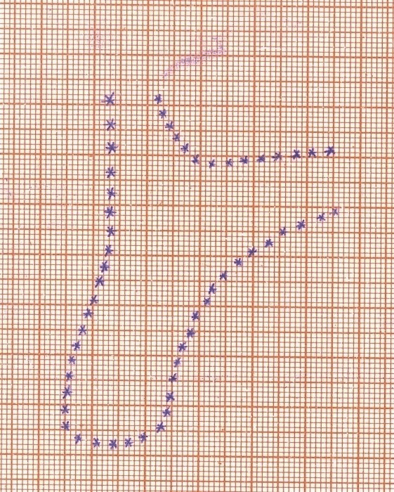
A CT scan was used as a reference to model the geometry of anterior maxillary region (Fig. 1). To create the digital image of the anterior maxilla, the CT image was transferred on to a graph sheet (Fig. 2). On the graph sheet the outline of the image was manually plotted and each point was converted into x, y and z coordinates. These coordinates were finally imported into the ANSYS software as keypoints of the definitive image. Finally spline curves were fitted through each set of key points, resulting in the final image of anterior maxilla.
The bone encountered in the anterior maxilla, classified as type 3 bone, was described by Lekholm and Zarb9 as a thin layer of cortical bone surrounding a dense trabecular bone of favorable strength. The thickness of the cortical bone was kept 1 mm and a uniform layer of cortical bone was modeled on the outer surface of the cancellous core (8, 9). The section of the model was extended mesially and distally in the z plane for 27.1 mm to get a three dimensional geometry. The labiolingual dimension of the alveolar ridge was 7.6mm mm. The anterior nasal spine-posterior nasal spine (ANS – PNS) line was oriented horizontally.
A simulated 13 mm × 4.2 mm root form implant made of titanium alloy (Ti-6Al-4V) was used for this study. The implant was opposed by cortical bone in the crestal region and by cancellous bone for the remainder of the implant bone interface. The abutments of three different angulations (0, 15 and 20 degrees) were connected to implant representing three restorative situations. The abutment was made of same alloy.
Since the primary goal of this study was to evaluate stress distribution at the implant abutment interface, the implant abutment complex was modeled as one piece structure and the crown restoration was omitted. The implant abutment complex was placed in the middle of the anterior maxillary right canine region. The platform of the implant was modeled as being flush with the alveolar ridge surface to mimic effectively a real clinical situation (10).
Mesh generation of the model
The basic principle of the FE analysis is to divide a problem domain into non overlapping finite number of small elements. It is achieved by replacing the continuum, by a set of key points called as nodes, which when properly connected form the elements. This collection of nodes and elements forms the finite element mesh. The mesh generation can be carried out either manually or automatically. The number of elements used in a problem depends mainly on the element type and accuracy desired. As a general rule, the. larger the number of nodes and elements, the more accurate is the finite element solution (11).
After placement of the implant abutment complex in the bone model, automatic mesh generation was done and the model was divided into large number of elements and nodes. The three-dimensional finite element model corresponding to the geometric model was meshed using ANSYS Pre-processor (ANSYS 11). The number of elements and nodes for each model is given in Table 1.
Specifying material properties
For the accurate analysis of the problem and interpretation of the results, two material properties were utilized i.e. Young’s modulus (elastic modulus) and Poisson’s ratio. The cortical bone, cancellous bone and implant with abutment were presumed to be linearly elastic, homogenous and isotropic. Although cortical bone has anisotropic material characteristics and possesses regional stiffness variation, they were modeled isotropically due to the unavailability of sufficient data and difficulty in establishing the principal axis of anisotropy. The corresponding elastic properties such as Young’s Modulus (€) and Poisson’s ratio (δ) of cortical bone, cancellous bone and implant were determined according to literature survey (8, 12) (Table 2).
Imposing boundary conditions
Before applying the boundary conditions, the system of equations is not completely defined. This is because, any model which is generated, has to be constrained depending upon the requirements of the study. Thus, boundary conditions are applied to have enough fixed nodal displacements to prevent the structure from moving in space as a rigid body when external loads are applied.
Interface condition
The bone implant interface was assumed to be perfect, simulating complete osseointegration. The implant and abutment were assumed to be connected as a single unit.
Load application
This is a part of the procedure where an attempt was made to simulate actual clinical situation. It was assumed that the magnitude of vertical force of 100N and horizontal force of 50 N was applied to the center of the top end of the abutment in the line of implant which is within the range of mean values reported in the literature (5).
After applying load on each model, a record of the patterns and values of stress developing around the implant in the bone was displayed using different colors showing different range of stress in cortical and cancellous bone.
View larger version :
[in a new window] |
Figure 2. Graphic representation of the CT Scan.
| |
View larger version :
[in a new window] |
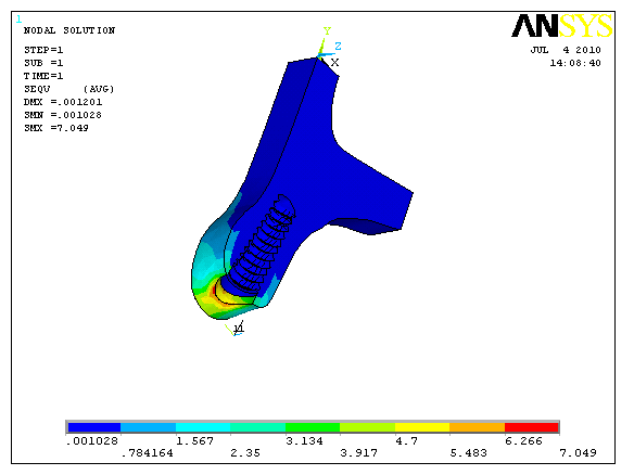
Figure 3. Vertical force on zero degree abutment showing stress concentrated on the labial surface of implant-abutment junction.
|
|
View larger version :
[in a new window] |
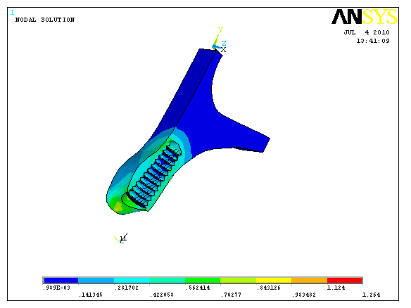
Figure 4. Vertical force on zero degree abutment showing concentration and distribution of force in cancellous bone.
|
|
View larger version :
[in a new window] |
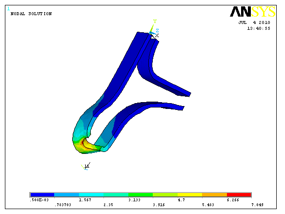
Figure 5. Vertical force on zero degree abutment showing stress concentration on the labial aspect in the implant-abutment junction in cortical bone.
|
|

View larger version :
[in a new window] |
Figure 6. Horizontal force on zero degree abutment showing stress concentration on labial aspect in the implant-abutment junction.
|
|
View larger version :
[in a new window] |
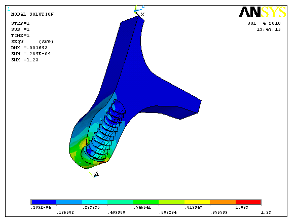
Figure 7. Horizontal force on zero degree abutment showing stress concentration on labial and lingual side in the implant-abutment junction in cancellous bone.
|
|
View larger version :
[in a new window] |
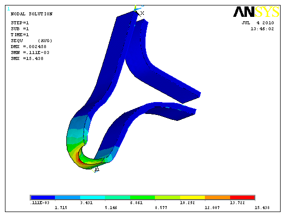
Figure 8. Horizontal force on zero degree abutment showing stress concentration in the implant-abutment junction in the cortical bone.
|
|
View larger version :
[in a new window] |
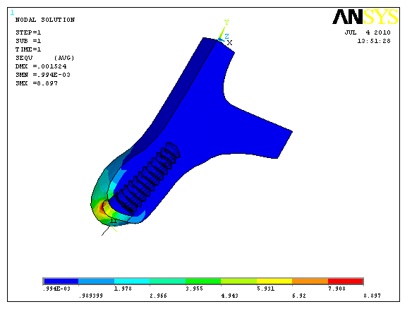
Figure 9. Vertical force on 15 degree abutment showing stress concentration at the implant-abutment interface on the labial aspect.
|
|
View larger version :
[in a new window] |
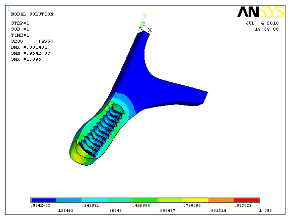
Figure 10. Vertical force on 15 degrees abutment showing stress concentration at the implant-abutment junction on labial side in the cancellous bone.
|
|
View larger version :
[in a new window] |
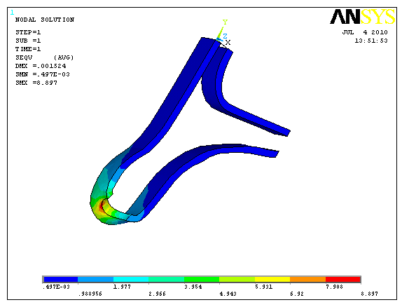
Figure 11. Vertical force on 15 degrees abutment showing stress concentration at the implant-abutment junction in the cortical bone.
|
|
View larger version :
[in a new window] |
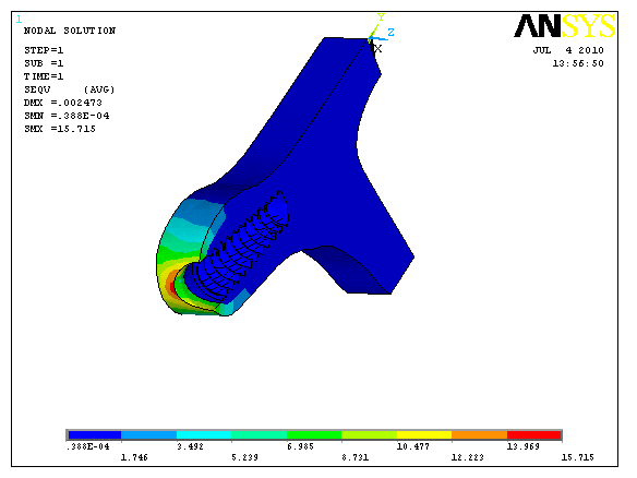
Figure 12. Horizontal force on 15 degrees abutment showing stress concentration on the labial aspect in the implant abutment junction.
|
|
View larger version :
[in a new window] |
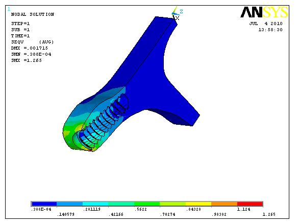
Figure 13. Horizontal force on 15 degree abutment showing stress concentration at the implant-abutment junction on the lingual and labial aspect in cancellous bone.
|
|
View larger version :
[in a new window] |
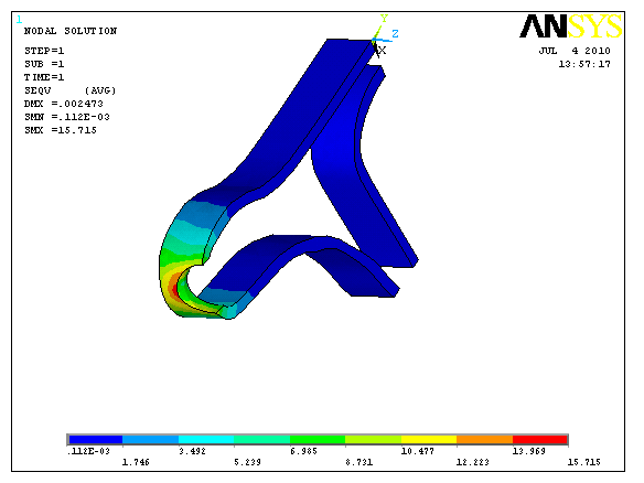
Figure 14. Horizontal force on 15 degrees abutment showing stress concentration on the labial aspect in the cortical bone.
|
|
View larger version :
[in a new window] |
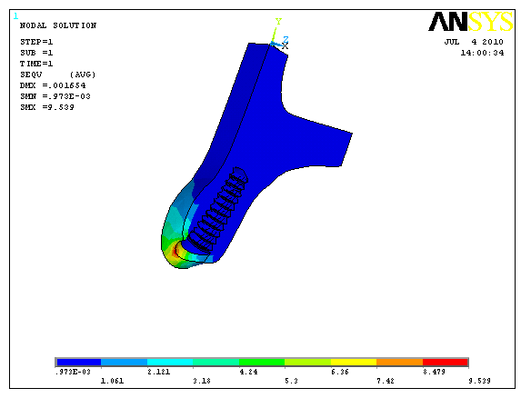
Figure 15. Vertical force on 20 degree abutment showing stress concentration at the implant-abutment junction on the labial aspect.
|
|
View larger version :
[in a new window] |
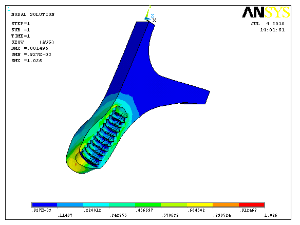
Figure 16. Vertical force on 20 degrees abutment showing stress concentration at the implant-abutment junction on the labial aspect in cancellous bone.
|
|
View larger version :
[in a new window] |
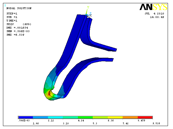
Figure 17. Vertical force on 20 degrees abutment showing stress concentration at the implant-abutment junction in the cortical bone.
|
|
View larger version :
[in a new window] |
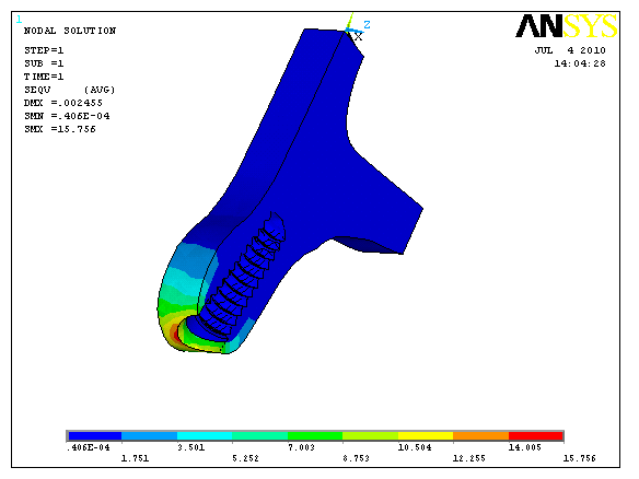
Figure 18. Horizontal force on 20 degrees abutment showing stress concentration at the implant abutment junction on the labial aspect.
|
|
View larger version :
[in a new window] |
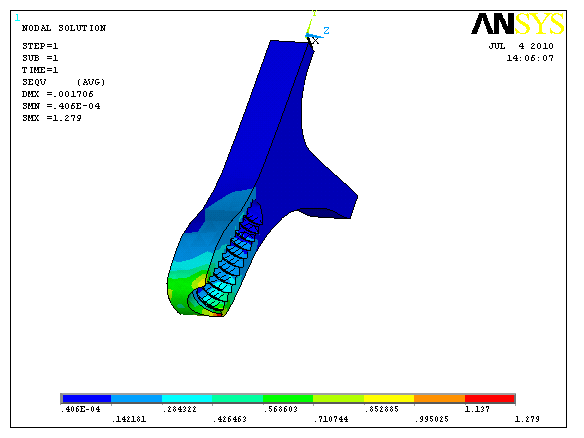
Figure 19. Horizontal force on 20 degrees abutment showing stress concentration at the implant abutment junction on the lingual and labial aspect in the cancellous bone.
|
|
View larger version :
[in a new window] |
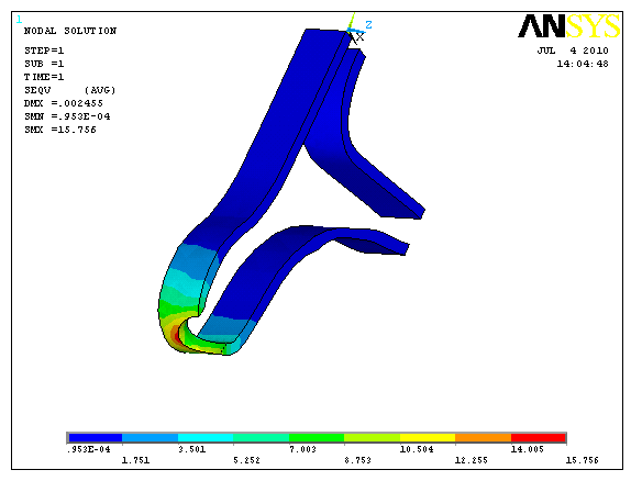
Figure 20. Horizontal force on 20 degrees abutment showing stress concentration on the labial aspect in the cortical bone.
|
|
|
|
RESULTS |
The study was conducted to analyze the distribution and values of stress generated in the bone around an implant with abutment placed in the right canine region of the anterior maxilla using different angulations of the abutment under vertical and horizontal force of 100 N and 50 N respectively. Stress was calculated using Von Mises criteria, which represented the distribution of stress in color-coded area.
Stress distribution
- Maximum Von Mises stress appeared to be located in the cortical bone surrounding the implant neck region on the labial side for a vertical force of 100 N for the angulated abutments;
- As the abutment angulation increased, the stress increased in both cortical and cancellous bone compared to straight abutments;
- For cortical bone the maximum stress was located around the implant neck and decreased towards the apical end of the implant for angulated abutments;
- For cancellous bone the maximum stress was located around the cervical to middle portion of the implant on the labial side;
- The stress concentration was also seen in the lingual and labial side for a horizontal force of 50 N in both cortical and cancellous bone.
Axial or Vertical load of 100 N
The maximum Von Mises stress was concentrated at the point of application of load i.e. at the top surface of straight abutment and distributed uniformly throughout the implant.
The maximum Von Mises stress was concentrated in the abutment, near the implant-abutment junction on the labial side for the angulated abutments.
Horizontal load of 50 N
Maximum Von Mises stress was concentrated in the abutment, near to the abutment implant junction on both labial and lingual regions and the distribution of stress was mainly at the labial and lingual regions of the abutment (Figure 3 - Figure 21) (Table 3 and Table 4).
View this table:
[in a new window]
|
Table 1. Number of elements and nodes for each model
| |
View this table:
[in a new window]
|
Table 2. Mechanical properties of different materials used in the Model
| |
View this table:
[in a new window]
|
Table 3. Von Mises stress (in Mpa) in the cortical bone under different masticatory forces
| |
View this table:
[in a new window]
|
Table 4. Von Mises stress (in MPa) in the cancellous bone under different masticatory forces
| |
|
|
SUMMARY & CONCLUSION |
A three-dimensional Finite Element Method was used to study the influence of abutment angulation on stress distribution pattern and their values in the cortical and cancellous bone around an implant in anterior maxillary right canine region. A geometric model of anterior maxillary right canine region was generated using CT scan data and a computer software program (ANSYS version 11). The CT image of anterior maxillary right canine region was traced on a graph sheet and then manually the key points were plotted. The key points were transferred to the ANSYS software and were joined to form the model geometry. The model was then extended 27.1 mm in z plane to create a 3 dimensional structure of anterior maxillary right canine region. Then a 3 dimensional finite element model of implant and abutment was constructed. The length of the implant was 13 mm and diameter was 4.2 mm. This simulated root form implant of dimensions 13 x 4.2 mm was embedded in the centre of the bone geometry. The platform of the implant was modeled as being flush with the alveolar ridge surface to mimic effectively a real clinical situation. Three types of angled abutments were connected to the inserted implant individually. The angulations of the abutments (0 degree, 15 degrees, and 20 degrees) were adopted from the commonly used pre-angled abutments available. Since the primary objective was to study the stress generated at implant bone interface, the implant and abutment were modeled as one piece structure. Material properties (Young’s modulus and Poisson’s ratio) and boundary conditions were applied. A vertical load of 100N and a horizontal load of 50N were applied to the top surface of the abutment for all the three clinical situations to simulate an actual clinical situation during function. The results were analyzed using Von Mises stress criteria.
Within the limitations of the methodology that was considered, the bone was homogenous and isotropic, the results of static load and linear analysis support the following conclusion:
- Maximum amount of stress concentration was observed in the cortical bone around the implant neck irrespective of the abutment angulation.
- The cortical bone plays a major role in the dissipation of stresses.
- The stress values for the angulated abutment were 4 to 5 times more as compared to straight abutment.
- The highest stress was generated with 20 degree abutment.
- The highest stress was below the elastic limit of the bone (approximately 60 Mpa) as described by Frost.
- The zero degree abutment produced the least amount of stress, so, as far as possible the implants should be placed along the axial loading direction of the proposed prosthesis.
- Combined with proper diagnosis and treatment planning, angulated abutments can be used in anterior maxilla to restore the implants placed at unfavorable angles without compromise of function.
Further studies are required to evaluate the stress with more variables such as bone density, interface conditions and degree of osseointegration. Finite Element Analysis is based on mathematical calculations, while living tissues are beyond the confines of set parameters and values, since biology is not a computable entity. Therefore, Finite Element Analysis should not be considered as a sole means of understanding the behavior of a geometrical structure in a given environment.
|
|
REFERENCES |
- Papavasiliou G, et al. Three-dimensional finite element analysis of stress-distribution around single tooth implants as a function of bony support, prosthesis type and loading during function. J. Prosthet Dent. 1996; 76: 633-640.
- Papavasiliou G, et al. Finite element analysis of ceramic abutment-restoration combinations for osseointegrated implants. Int. J. Prosthodont. 1996; 9: 254-260.
- Eger DE, Gunsolley JC, Feldman S. Comparison of angled and standard abutments and their effect on clinical outcomes: A preliminary report. Int. J. Oral Maxillofac Implants. 2000; 15: 819-823.
- Ten Bruggenkate CM, et al. Indications for angled implants. J. Prosthet Dent. 1992; 67: 85-93.
- Canay S, et al. Comparison of stress distribution around vertical and angled implants with finite element analysis. Quintessence Int. 1996; 27: 591-598.
- Reiger MR, Mayberry M, Brose MO. Finite element analysis of six endosseous implants. J. Prosthet Dent. 1990; 63: 671-676.
- Meijer HJA, et al. Stress distribution around dental implants: Influence of superstructure, length of implants and height of mandible. J. Prosthet Dent. 1992; 68: 96-102.
- Ashok S, Thomas Kaus, Peter Sochor. The use of angulated abutments in implant dentistry: Five-year clinical results of an ongoing prospective study. Int. J. Oral Maxillofac Implants. 2000; 15: 801-810.
- Fanuscu MI, Chang TL. Three-dimensional morphometric analysis of human cadaver bone: microstructural data from maxilla and mandible. Clin. Oral. Impl. Res. 2004; 15: 213-218.
- Chun HJ. Evaluation of design parameters of osseointegrated dental implants using finite element analysis. Journal of Oral Rehabilitation. 2002; 29: 565-574.
- Vasudeva G. Finite element analysis: A boon to dental research. The Internet Journal of Dental Sciences. 2009; 6 (2).
- Geng, et al. Application of finite element analysis in implant dentistry: A review of literature. J. Prosthet Dent. 2001; 85: 585-598.